The circuits in a device correspond to what one could call a device "poles". These circuits are used in the symbol definition, and also in the manufacturer part definition. Cross references are generated, and terminals are shown by comparing the circuits of the symbol and the circuits of the manufacturer part.
The circuits are not limited to devices. Terminals and PLC cards can also have circuits.
The software manages several types of circuit, corresponding to the nature of the electrical component.
For example, a three-pole circuit breaker consists of three Circuit breaker, Switch circuits.
|
|
|
The circuits of a component are the sum of the circuits of all the symbols representing this component.
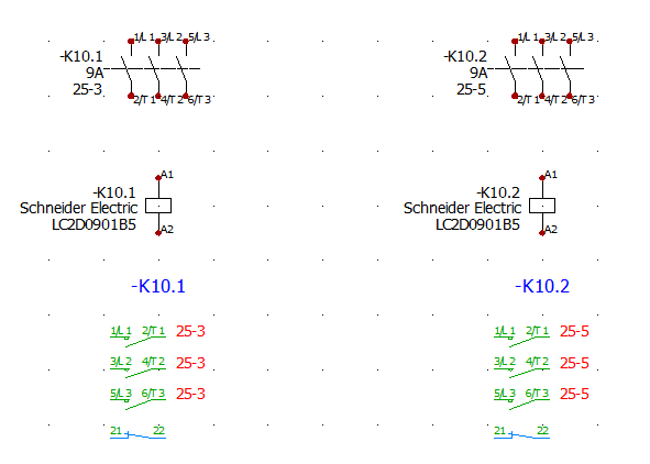
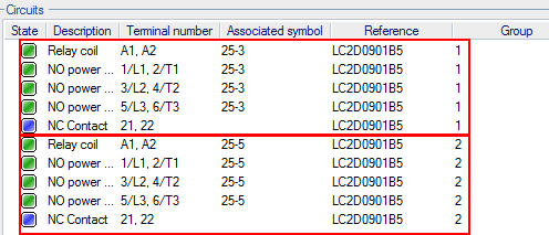
The above example shows the definition of reference LC1D09006B7 from Schneider in circuit terms. It consists of a coil, a 3-pole power contactor, NO and NC contacts.
When a manufacturer part is assigned, the softwarecompares the circuits of the manufacturer part and the circuits of the various symbols representing the component. If they match, the numbers of the material terminals are automatically propagated to the symbol circuits and displayed in the scheme. If there are any differences between the circuits of the manufacturer part and the circuits of the symbols, the circuits are added together and reserved. The numbers of the material terminals are not displayed on the scheme.
As seen in Configuration of cross references, some types of circuits are associated with a cross references thumbnail (graphic symbol). These are circuits associated with a Child or Same level symbol (Parent symbols do not generate cross references thumbnails).
When cross references thumbnails are generated, the softwarelists all circuits associated with the component, filters them to retain only the Child or Same level circuits, and uses the cross references thumbnail associated with the type of circuit to generate the graphics. The numbers of the material terminals are automatically added, as is the position of the symbols in the project and drawings.
|
|
|
In the above example, there are 3 NO power contact type circuits in column 4 of drawing 10 and one NO contact in column 4 of drawing 04. The NC contact belonging to the manufacturer part is not used in the drawing (it is placed in reserve instead). The second NO contact (column 6 of drawing 04) is not part of the manufacturer part.
To associate circuits, enter a number (or a name) on each circuit. To associate circuits, they must have the same number.
For example, a reversing contactor uses the circuit groups, on which you can find one coil associated to one contactor and a second coil associated to a second contactor.
|
|
|
The manufacturer part data stores the group number. When you insert the symbol component, the cross references are automatically updated with the group number.
|
Related topics:
Cross references configuration
|